Technical materials
Operating principle
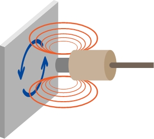
GAP-SENSOR is generally called “eddy current sensor”. It generates high-frequency magnetic field by flowing high-frequency current to a coil inside a sensor head. When a measuring object(conductor) come close to the magnetic field, eddy current is generated on the surface of the measuring object, and impedance of the sensor coil changes. We detect and use the change of transmission strength by the phenomenon to get a relationship between displacement and voltage.
Materials, dimensions, shapes of measuring target
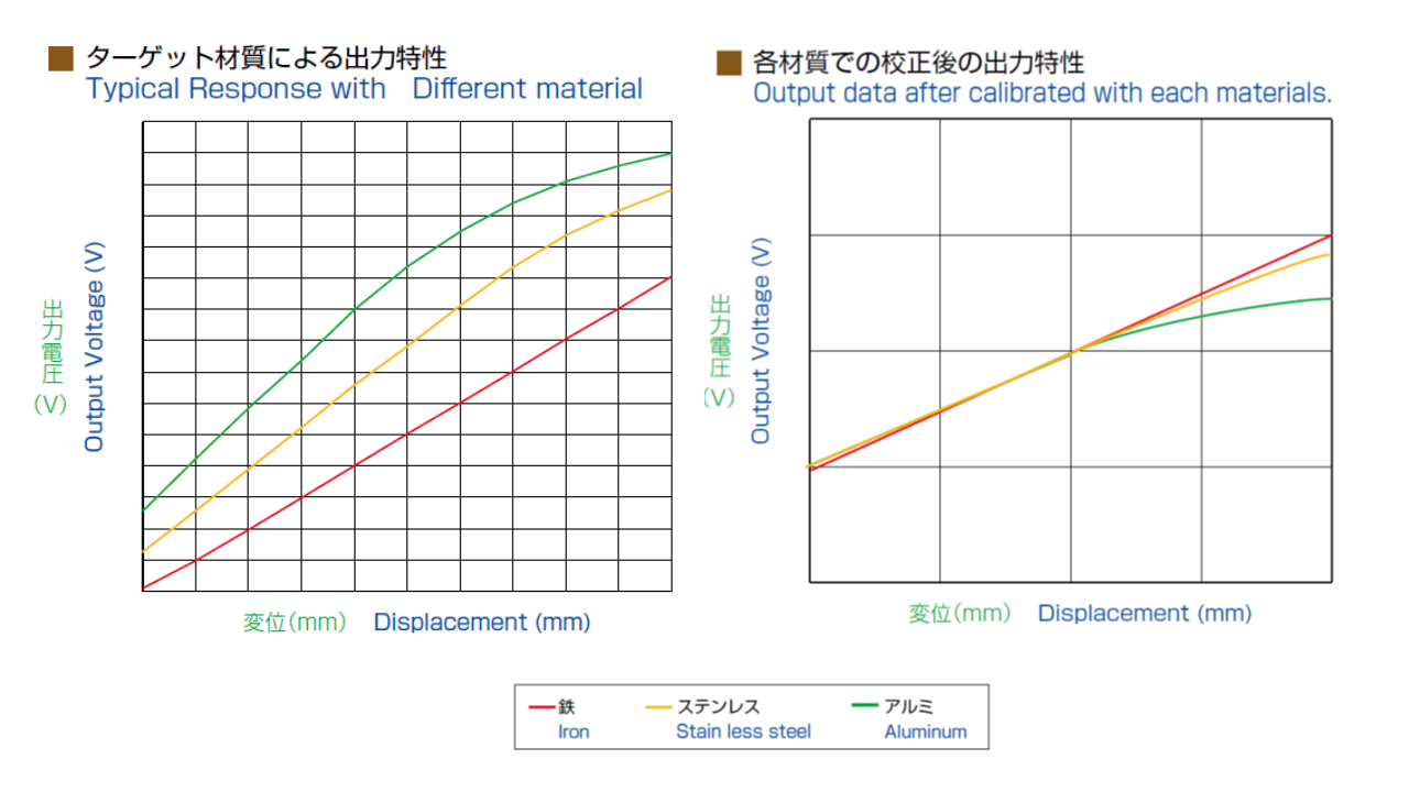
Output characteristic according to materials
Gap sensor works if a measuring target is metal, but the measuring range and sensitivity of the sensor differ according to the material of the target.
 |
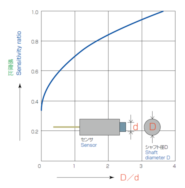
Dimension of measuring target
A measuring target is recommended to be three times or more as big dimension as the diameter of the sensor. If the surface of the target is less than that, the sensitivity of the sensor lower. In addition, in case of that the measuring target is powder, laminated or a bundle cotton, the sensitivity of the sensor also lower, and the measurement might end in failure.
Thickness of measuring target(in case of PU-05)
Thickness of the measuring target is recommended to be more than 0.2mm in iron(SCM440), 0.4mm in Aluminum(A5052P) and 0.3mm in copper(C1100P).
Shape of measuring target
When the target is cylindrical (e.g.,shaft) and its diameter is at least 3.5 times as large as the sensor coil, the sensitivity is not affected by the shape of the target.If the ration between the sensor coil and the target is one to one, the sensitivity decrease to about 70%.
 |
RUN-OUT phenomenon
In measurement of axis vibration, the output which does not correspond to true value might be observed. This is called “RUN-OUT phenomenon”.
The mechanical RUN-OUT which is attributed to scratches, unevenness, ellipsoid, eccentricity, etc. of the surface of the target can be prevented by correction polishing.
For the electrical RUN-OUT observed in axis vibration measurement which is magnetic substances and particularly steel, the causes are simple and have been considered as remaining magnetism, uneven crystalline structure and dispersed quenching hardness of the steel material surface. According to an object for measurement, countermeasures as shown below might be necessary.
- Demagnetize a measuring target after machining
- Decrease compressive stress from a target
- Stick a copper sheet around a target and polish it
- Change a target material from steel to copper or any appropriate materials
Sensor mounting
Surrounding environment about sensor
When a metallic material other than a target exists close to a detection surface of gap sensor or the sensor is embedded into a metallic part, enough distance between the metal and sensor should be provided as shown below.

※画像をクリックして拡大表示
Interference between sensors

※画像をクリックして拡大表示
When multiple sensors are closely mounted in multi-channel simultaneous measurement, the sensors interfere with each other and it cause error in the result. It is recommended to provide enough distance between the sensors (generally six times as large as the sensor diameter), to use different types of sensors or to use an interference preventive converter for avoiding interference.
Feel free to contact us about it.
*When using the interference preventive converter, required distance between the sensors is twice as large as the sensor diameter.
Dead zone(α0)
Gap sensor (except some sensor models) has a dead zone(α0). The dead zone expresses the distance that the output characteristic of a sensor does not keep linearity. In our catalog, the measuring distance of 0mm include dead zone(α0).

※画像をクリックして拡大表示
Adjustment of output
The output characteristic of gap sensor vary depending on the material or shape of a target. However, it is possible to maximize the performance of the sensor through the adjustment of sensitivity.
Arrangement of adjustment volume

※画像をクリックして拡大表示
55 type / 76 type converter
Adjustment volume are located inside the converter. Please detach an upper cover from the converter.
MS type converter
Adjustment volumes of GAIN, ZERO(SHIFT) and LINEAR are located in the front side of the converter.
Use senser select function according to the sensor type. Adjustment volume of sensor select function is located in the back side of the converter.
55HFL type/ 37 type/ CFC type converter
Adjustment volume is located in the opposite side of a terminal block.
Adjustment of gap sensor output (55 series sensor)
※画像をクリックして拡大表示
CAL(GAIN)
Possible to set to optimum output voltage which is easily calculated with sensitivity volume changing output voltage against displacement.

※画像をクリックして拡大表示
SHIFT(ZERO)
Possible to adjust shift of output voltage without changing sensitivity.

※画像をクリックして拡大表示
LINEAR
Compensation for the linearity range of output. Once the linearity is adjusted, readjustment of sensitivity and shift is necessary.
Procedure of adjustment
*About dead zone(α0), refer to the below sensor specifications list.
*Adjusted voltage value should be within the range of linearity.
*Full scale means the maximum measuring range of a sensor. ex.) Full scale of PU-05 is 2mm.
0〜5V output model(PU-01~PU-03A)(PF-02/PF-03)
- Set the gap between the sensor and target to 0mm plus dead zone and then adjust the voltage to 0V with SHIFT.
- Set the gap between the sensor and target to the 1/2 full-scall and then adjust the voltage to the 1/2 full-scall voltage with CAL.
- Set the gap between the sensor and target to the full-scall and then adjust the voltage to the full-scall voltage with LINEAR.
- If adjust with LINEAR, check the voltage at each gap of when adjusted with SHIFT and CAL. If the voltage is out of the range of linearity, repeat adjustment from the first step. If the voltage is within the range of linearity, the adjustment procedure is completed.
± 5V Output model(PU-05~PU-40)
(DPU-10A~DPU-40A)
- The definition here of 0mm point is where set the gap between the sensor and target to 0mm plus dead zone.
- Set the gap between the sensor and target to the value of the 1/2 full-scall and then adjust the voltage to nearly 0V with SHIFT.
- Set the gap between the sensor and target to the value of the 1/4 full-scall and then adjust the voltage to nearly -2.5V with CAL.
- Set the gap between the sensor and target to the value of the 3/4 full-scall and then adjust the voltage to nearly +2.5V with LINEAR.
- If adjust with LINEAR, check the voltage at each gap of when adjusted with SHIFT and CAL. If the voltage is out of the range of linearity, repeat adjustment from the first step. If the voltage is within the range of linearity, the adjustment procedure is completed.
1~5V output model (S-06/S-10)
- The definition here of 0mm point is where set the gap between the sensor and target to 0mm plus dead zone.
- Set the gap between the sensor and target to the value of the 1/8 full-scall and then adjust the voltage to nearly 1.5V with SHIFT.
- Set the gap between the sensor and target to the value of the 1/2 full-scall and then adjust the voltage to nearly 3V with CAL.
- Check the voltage at each gap of when adjusted with SHIFT and CAL. Repeat adjustment until each voltage become regulated value.
- Adjust with LINEAR after complete adjustment with SHIFT and CAL.
- Set the gap between the sensor and target to the value of the 7/8 full-scall and then adjust the voltage to nearly 4.5V with LINEAR.
- Check again the voltage at each gap of when adjusted with SHIFT and CAL and then adjust it within the range of linearity.
- Check again the voltage at the gap of when adjusted with LINEAR. If the voltage is within the range of linearity, the adjustment is completed. If it is out of the range, repeat from the first step of the adjustment.
In case of AEC-7606(Full scale : 2.4㎜)
| Gap | Output | Adjustment volume |
| 0.3㎜+0.1㎜ | 1.5V | SHIFT |
| 1.2㎜+0.1㎜ | 3.0V | CAL |
| 2.1㎜+0.1㎜ | 4.5V | LINEAR |
Sensor specifications list(Simplified ver )
| Sensor model | Output(V) | Measuring range (Iron)(㎜) |
Dead zone (α0)(㎜) |
| PU-01 | 0~1.5 | 0~0.15 | 0 |
| PU-015A | 0~3 | 0~0.3 | 0 |
| PU-02A | 0~2.5 | 0~0.5 | 0 |
| PU-03A | 0~5 | 0~1 | 0 |
| PU-05 | ±5 | 0~2 | 0.05 |
| PU-07 | ±5 | 0~3 | 0.1 |
| PU-09 | ±5 | 0~4 | 0.2 |
| PU-14 | ±5 | 0~6 | 0.3 |
| PU-20 | ±5 | 0~8 | 0.4 |
| PU-30 | ±5 | 0~12 | 0.6 |
| PU-40 | ±5 | 0~16 | 0.8 |
| PF-02 | 0~2.5 | 0~0.5 | 0 |
| PF-03 | 0~5 | 0~1 | 0 |
| DPU-10A | ±5 | 0~5 | 0 |
| DPU-20A | ±5 | 0~10 | 0 |
| DPU-30A | ±5 | 0~15 | 0 |
| DPU-40A | ±5 | 0~20 | 0 |
| S-06 | 1~5 | 0~2.4 | 0.1 |
| S-10 | 1~5 | 0~4 | 0.1 |
Glossary
Resolution
Even when a target is at a standstill, the voltage from a converter changes minutely due to the residual noise inside the converter. The lower noise there is, the more measuring accuracy is improved with high resolution. We measure the noise level at the half scale point of the sensor measuring range, and convert it into displacement to define the result value as resolution.
Linearity

※画像をクリックして拡大表示
The output voltage of the displacement sensor is proportional to the gap from a target. However, the plotted line from actual measurement deviates from the ideal line. The difference between actual and ideal lines is expressed in percentage against the full scall of the sensor measuring range.
*The value in the catalog are based on the room temperature.
Measuring range
Measuring range means that a sensor can measure displacement of a target. The gap between the sensor and target is proportional to voltage output within this range. It is possible to measure the target behavior beyond the specified measuring range by changing sensitivity because of the sensor characteristic.
*The value in the catalog is based on the case when measuring target is iron.
Frequency characteristic
Frequency characteristic means the frequency band which can measure vibration, displacement and rotational speed of a target with our sensor.
Temperature characteristic
Sensor sensitivity depend on surrounding temperature of the sensor. This is called temperature drift. The temperature drift means the change of sensitivity per 1℃.
PF series sensors feature minimum temperature drift among our gap sensor products